I often participate in a forum that I highly recommend as reading material for anybody interested in golf cart repair or modifications (upgrades). It is called Cartaholics and here is a link to it: Cartaholics Golf Cart Forum | Cartaholics Golf Cart Forum . People generally write to the forum for help with their problems with their golf carts and a bunch of us contributors try to help answer their questions. As a matter of fact, any member can render their opinion and it’s super easy to join and doesn’t cost anything to be a part of. You really ought to check it out.
Anyway, recently, a new member wrote in with a “way too familiar” problem. He was having trouble getting the electric motor off of the splines of the input shaft of the differential of his cart. It is almost always at least a “pain” to get the motor off, but usually with enough penetrating oil, banging around with a rubber hammer (so as not to damage anything), and prying wherever you can and as carefully as you can, it will let go and come off. However, there are always some exceptions. I worked on golf carts professionally for many years (I don’t want to admit how many) and during that period of time, I came across two where the motor just wouldn’t budge, no matter what I did. You are usually trying to get the motor off in order to replace the brushes, the commentator bearing, or perhaps a broken terminal. Of course, it is highly recommended that you have the commentator “turned” on a metal lathe while you’re at it, especially if it is “roughed up” quite a bit.
So, what do you do if you can’t get the motor off of the shaft? Is it possible to “re-do” the motor right there on the shaft? The answer is YES! It certainly isn’t as easy as it would be if you had the motor laying out on a bench, but you can do it if you have enough patience and mechanical aptitude. The following is a “run down” on how I did it (more than once).
First off, I jacked the rear end of the cart up, but only on the side that the motor was mounted toward (the side nearest the direction that I needed to pull the motor off toward). Then I took the wheel off of that side also. Of course, I had already removed the wiring from the battery pack’s B+ and from the motor, carefully marking each wire as to where it was going to go back to when reassembled (A1, A2, S1, S2, and B+).
Next, I removed the “end cap” off of the motor. When you look at the end cap, you will find two fairly large bolts (usually 10mm heads) that run the length of the motor and actually secure the end cap through the motor to the other end of the motor’s frame or housing. I always use a wrench on them and “tap” on the wrench with a hammer to “knock” them loose, rather than just using brute force on the wrench. It seems to prevent stripping or breaking the bolts. Then I remove the bolts that hold the commutator bearing retainer in place. If you look at the end cap, in addition to the 10mm “frame bolts”, these retainer bolts will be closer to the center and there will be either two or three of them. They usually have Phillips type heads on them and they are extremely easy to strip the head off of. Therefore, I use a hand held “impact driver” to remove them. This is the type of impact driver that you hold with one hand and tap on the end of with a hammer (not a pneumatic driver). It “twists” the head of the screw as it gets pushed into it so that it won’t strip the head out. You have much more control over what you are doing with this type of impact driver for “light” work. Harbor freight sells one that is small (about 5 inches long and does a wonderful job). Removing these bolts allows the retainer to fall back toward the commentator so that I can tap the end cap off of the armature. When tapping it off, you are really doing two things. First, you are pulling the cap off of the commutator bearing. It is a “slight” press fit, more of a “slide” press fit and won’t offer too much resistance, but a little. Just tap on one side and then the other side, back and forth to work the cap off. The second thing you are doing is pulling the brushes over the end of the commentator. They are “spring loaded” to where they touch the commentator by their individual holder springs, so when the cap comes off, they will slide toward the center of the armature. That is fine. They will be repositioned later during the reassembly procedure.
So now, I have the cap (with the brushes in it) removed and the motor housing and the armature is still hanging there on the input shaft. Looking at the armature, I can see the bearing retainer hanging there behind the bearing. That is where the bolts that I removed from the cap were seated. It holds the bearing firmly in place (when bolted in) to prevent the bearing from moving in or out or spinning.
I want to replace the commentator bearing, so I have to pull it off of the end of the armature shaft. I have a bearing puller that really works good for that. It came from Harbor Freight and looks like this:
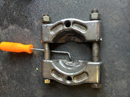
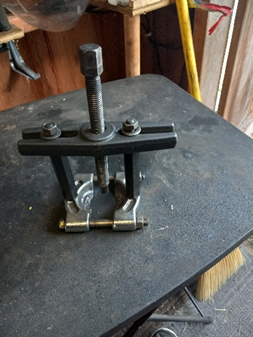
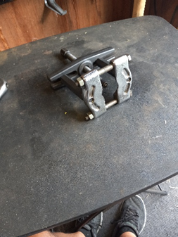
The problem with most pullers for this job is that you can’t get the jaw of the puller behind the bearing (between the bearing and the front of the armature). Especially the three-jaw type. The “pulling” ends of the jaws are just too thick to fit in there. In the first picture, I pointed a yellow handled pick at an area of the puller that I ground down just a little to make it easier to get in that space. It slips in behind the bearing and easily pulls it off of the end of the shaft. When I remove the bearing, I make sure that I note which way the retainer is facing. It may or not be “directional” and needs to be replaced facing the same direction it was.
Next, I deal with the commentator. They always have lines worn in them from the brushes and they need to be cleaned up and smoothed out. Here is where I would normally take the armature to the metal lathe and turn it down to remove the lines and then polish it up, but I can’t so that with the armature hanging on the end of the input shaft, I have to improvise. I find a socket the size of the hub nut on the axle that I have just removed the wheel from and then enlist the help of my wife (or whoever is handy) to run a drill motor to spin that axle. Of course, it needs to be a variable speed drill because I don’t want to go very fast. I also have to help get it going by rotating the armature while she is trying to get the drill to start spinning. Normally, if the other wheel was off of the ground, as she spun the axle she is working on, the other axle would simply spin in the opposite direction (due to the differential), but it can’t because it has the weight of the cart pushing down on its tire. If you have both wheels off of the ground, you will have to hold the other tire in place with something. That forces the spinning of the axle to make the input shaft of the differential (and therefore the armature of the motor) spin. You would be surprised how “true” it spins. The differentials input shaft bearing does a nice job of keeping it true. While she is spinning the axle, I take a small, fine (but very sharp) file and hold it against the commentator, until I get it reasonably smooth. No, it won’t be as good as turning it on the lathe, but it will have to suffice. I then clean out the grooves between the “bars” of the commentator because as the file cuts the soft metal, it tends to compress some of the shavings into the grooves where the insulators are that separate the bars. I use a small “pick” and carefully run it down each groove to remove the metal. I then have her spin the shaft again and repeat the process using light emery cloth to further polish the commentator.
Once I’m happy with the commentator (and tired of listening to my wife complain about her role in the project), I’m ready to replace the bearing. BE SURE to put the bearing retainer on the shaft behind the bearing first. It just hangs there for now and will be tightened back against the bearing a little later. As I mentioned before, some of the retainers are directional and need to be reinstalled facing the right direction. Some of them have a slightly raised “ring” on one side that will touch the bearing before the rest of the retainer does and some don’t have that, so just be aware that it needs to go back the same way it came off.
To reinstall the bearing, this is where I would usually take the armature over to the hydraulic press and push it on. Unfortunately, I don’t have that option with the armature hanging on the input shaft, so I have to “drive” it into place. It isn’t that big a deal. I just place the bearing on the end of the shaft and tap it VERY lightly with a plastic hammer enough to get it to stick to the end of the shaft. I then find a socket that will be able to fit over the shaft and line up with the INNER race of the bearing (NOT the outer race). The bearing can then be driven on with a few good “raps” with a heavy hammer. If I pounded on the outer race, I might damage the bearing by “flexing” it during the process.
At this point, I go back to the cap that has been removed and replace the brushes. It is very important to study the exact routing of the old brushes’ connecting wires. When I place the new brush in its holder, I don’t want the wire to touch anything that will “short” it to the case. Another issue here is that when you try to get the screws out that hold the connecting wires of the brushes out, they may be so tight that the whole “post” that the screw is attached to may try to bend. To fix that, I use something to hold the post in place (like a pair of pliers or a wedge of some type) while I’m loosening the screw.
Now, after the new brushes are installed, the trick is to reposition the new brushes to where we can release them on to the commentator after we start to replace the cap. So, what I do is pull the spring back to where I can push the brush up in the holder that it slides back and forth in so that the side of the brush sticks up to where I can place the end of the spring against the side of the brush to hold it in place until I am ready to let the brush fall in place against the commentator.
So, now I have the brushes prepositioned in the cap and I am ready to put the cap back on. The bearing retainer is just hanging there and is ready to be pulled back into place by its bolts. But here is where I have a problem. The bolts that hold the retainer in place are intentionally very short so that when they are in place (sticking through the retainer), they won’t stick into the front of the commentator. So, I have to find a bolt that is the same diameter and pitch as the ones I took out, but much longer. That way I can reach the retainer with the longer bolt and “pull” it towards the cap as I do the reassembly. So, I place the housing back over the armature and tap the cap lightly over the end of the bearing and then stick the longer bolt that I have found through the hole that the shorter ones will go through and start it threading into the retainer in one of its holes.
Now, the fun begins. As I start to tap the cap into position (remember the slip fit over the bearing), when I get to the point that the brushes are over a reasonable amount of the commentator surface I smoothed out, I need to release them and then continue to tap the cap over the bearing until I can get the larger bolts that I took out (the ones with the 10mm heads) back into position. I will use them to pull things back together as I “walk” the retainer along with the longer retainer bolt I found that is sticking through its hole. I can reach back into the brush holder area with a long pick or something similar where I can remove the pressure of the springs of the brush holders that are lodged against the side of the brushes and let them fall into place and then guide the springs into the grooves that are provided for them in the end of the brushes. Once the cap is tapped and pulled (with the larger bolts) back over the bearing, everything is in place except the retainer. It is sitting behind the bearing and is ready to be positioned with the bolt that is sticking out to where the other bolt can be installed. I look through the remaining hole with a flashlight and manipulate the retainer back and forth with the longer bolt that I have sticking out until I can see that the retainer’s other hole is lined up with the remaining bolt hole and then screw the remaining bolt lightly into the retainer. This step takes some patience. Because of the length of the shorter bolts, I have to sort of “pull” the retainer toward the bearing with the bolt that is sticking out, and “fish” around with the shorter bolt until I finally get it to start. It’s then time to remove the longer bolt that we found and replace it with the other shorter bolt that I have left. Remember, there may be either two or maybe three of these bolts. But, either way, it’s the same routine. I use the longer bolt that I found to guide and manipulate the retainer around until I can get the other one or two bolts to line up with the remaining hole(s) in the retainer and then install them and remove the longer bolt and replace it with one of the originals. Then it’s just a matter of tightening things down and testing the motor with a good ohm (continuity) meter.
If everything went well, the meter will show a very low resistance (good continuity) between S1 and S2 (between .5 and 1 ohm or so). That verifies that the field is in one piece (no openings). It should be fine; I didn’t do anything to it. The meter should also show continuity between A1 and A2 (again in the neighborhood of less than an ohm). That proves that the brushes are, indeed, resting on the armature and the armature has no openings in its windings. Since the A1 to A2 test is through the brushes, it gives me an assurance that the brushes are now where they should be. And, that’s all there is to it! Good luck, Ron.
For information about books written by Ron Staley about both electric and gas driven golf carts and their repair, visit the following links.
Electric Golf Cart Repair, both as an eBook and in Hardcopy:
Book: Ronald L Staley: 9780578560557: Amazon.com: Books
Gas Golf Cart Repair, both as an eBook and in Hardcopy:Gas Golf Cart Repair Book: Ron Staley: 9798987911303: Amazon.com: Books