In the last post of this sequence, we talked about carts using an electronic speed controller instead of resistors to control the speed of the motor. We discussed the technique that the motor speed controllers use to vary the voltage to the motor. The technique is called Pulse Width Modulation (PWM). In order to know how much modulation the controller needs to supply at any given time, it must have input from the driver of the cart. That is what we will talk about in this post. Where does it get this information from? Keep in mind that we are still talking about SERIES wired electric carts. We will get to the “shunt” or “sepex” type carts later.
I copied the following diagram from a book that I wrote called Electric Golf Cart Repair 101 (and a half). There is a link at the bottom of this post if you are interested in information about the book. We’ll go through the need for each of the components in this post.
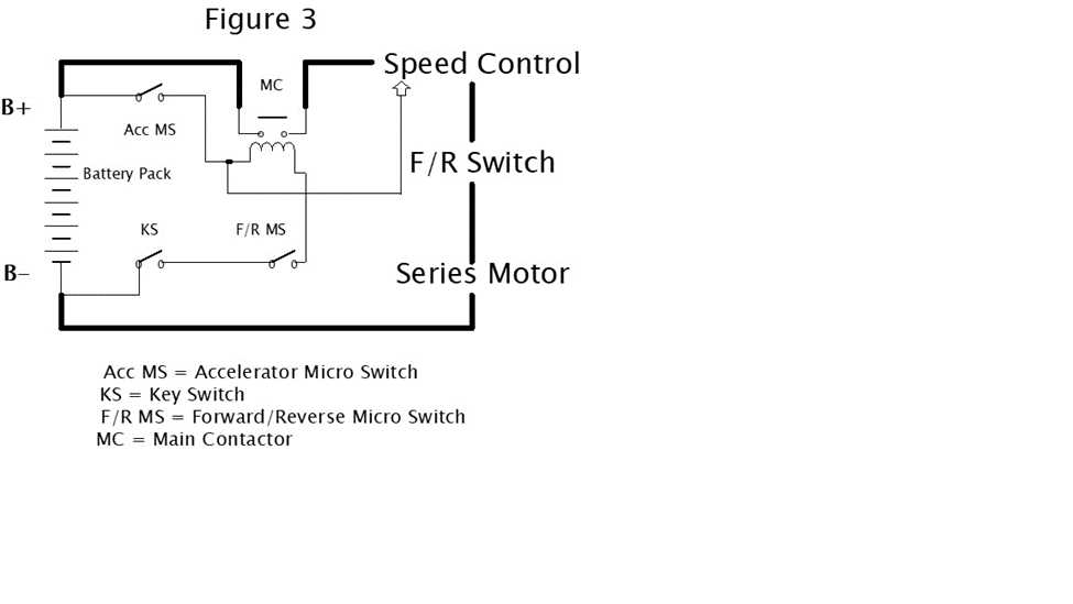
Toward the top and in the middle of the diagram is a thing referred to as the MC. As the ledger states, another name for the MC is the Main Contactor. It is actually what we have been calling the solenoid, so we’ll stick with that name. I always think of the solenoid as the “center” of operation of an electric golf cart. It is where two “worlds” meet. We’ll refer to the two worlds as the “low energy world” and the “high energy world”. The solenoid contains two circuits within itself. It consists of a coil circuit (low energy circuit) that when supplied with current creates a highly magnetic field. This magnetic field moves a “contact bar” internally that causes two contacts to short together (high energy circuit).
Notice that the wires to the coil side of the solenoid (lower part) are depicted on the diagram with smaller lines (smaller wires). That is because these wires carry (conduct) very little current compared to the larger wires depicted on the contact side (upper part) of the solenoid. It only takes a few milliamps of current through the coil of the solenoid to energize it (make it short the contacts on the high energy side together). That is very important because it allows us to use smaller wire and less “heavy” switches to perform what I call the “logic” switching. The logic (low energy) circuitry on our diagram includes the KS (Key Switch), the F/R MS (Forward/Reverse Microswitch) and the Acc MS (Accelerator Microswitch). Note that the F/R MS is a small switch that is activated when the regular F/R switch (the large one that you move with your hand) is moved into either forward or reverse. Until all three of these switches are activated (make closure), the cart can’t move because the battery pack isn’t connected to the high energy circuitry due to the unenergized solenoid. That is quite intentional and prevents the cart from moving before we want it to. Once the three switches are “happy”, the controller is ready to go. Notice that there is a small wire from the logic circuitry to the controller. It provides a “trigger” signal to the controller. The next diagram is of a typical older Club Car with an electronic speed controller.
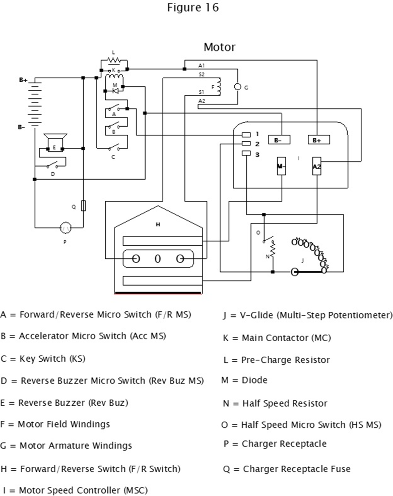
Toward the top and to the right is the Motor Speed Controller. It is designated as “I” in the drawing. The parts that I want to talk about are the three connections to it in its upper lefthand corner. They are labeled pins 1, 2 and 3. Earlier I mentioned that when the three logic switches are activated in order to energize the solenoid, there was a “trigger” signal to the controller to let it know that the system was ready to go. That is it on pin 1. Pins 2 and 3 are where the throttle position sensor input comes into the controller. In the case of our example in the drawing, the signal comes from a device called a multi-step potentiometer. It looks from the outside just like the V-glide that was used in the model we talked about in the previous post, but instead of providing switching for the high energy circuitry, in this case it provides a low energy signal to the controller to tell it where the throttle is positioned at any given time. As I mentioned before, this input could come from a conventional potentiometer, or even an inductive device, depending on the design of the cart. Once again, for a detailed description of exactly how the system works, I recommend the book that is referenced at the end of this post. The controller uses the PW technology that we discussed in the last post to vary the bursts of energy (and therefore the average voltage) that are supplied to the motor. Thereby, the speed of the motor is varied without dissipating any energy by heating up resistors.
In our next post of this sequence, we will go into another type of motor speed controller. It will be the one that is used in “shunt” (sometimes called sepex) systems. They are significantly more complex but offer many advantages over the “series” type systems. See you next time, Ron.