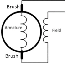
In the last post, we discussed carts with the most sophisticated “series” speed control systems. The controllers contained microprocessors and were capable of being “programmed” to fit the needs of the cart and its driver. What do we mean by “series”? There are two major components within a DC motor that make things work. They are the “stator” and the “rotor”. They both consist of many coils of wire, which when energized by allowing an electrical current flow through them, create very strong magnetic fields. They two forces are placed in opposition to each other (within the motor) in such a fashion as to cause the rotor (also referred to as the armature) to spin inside of the case of the motor where the stator (also referred to as the field) is attached. The energy provided to the rotor is supplied through a part of it called the commutator. The “brushes” provide the physical contact of the circuit to the armature. The brushes “rub” on the commutator as the armature spins, thereby providing a continuous supply of energy to the armature.
The following diagram would represent how the armature and the field coils are connected in a series relationship:
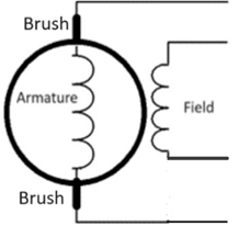
The wires at the top righthand corner then go off to the speed controller, forward/reversing system, solenoid, etc.
In the next diagram, both the armature and the field connectors go back to the speed controller as individual pairs. The controller then supplies the reversing and also operates the solenoid.
With the shunt system, the current that flows through the field coil can be manipulated, no matter what is going on with the rotor (armature) circuitry. This offers a lot more flexibility in the design of the speed controller. So, even if the voltage to the armature is lowered by an increased load, (like going up a hill) the current flow through the field can be independently maintained or enhanced by the controller. The process of altering the current flow through the field coil for different diving conditions and to match other unique requirements of the cart’s hardware (motor, tire size, required torque and speed) is referred to a “field mapping”. The manufacturer can allow more sophisticated options to improve and customize the cart’s performance.
In general, here are some of the advantages of a shunt motor and speed control system:
In addition to the field and armature connections, a shunt motor has a cable connected to the end of the motor that goes to a speed sensor, so the controller “knows” how fast the motor is spinning at all times. This is very helpful information that can be used to ensure the correct performance of the cart.
Shunt motors can provide more torque at “take off” due to the fact that the current flowing through the field winding is not limited to that of the armature (it is supplied separately from the controller).
The shunt motor can be used to produce “motor braking”. That means that when you go down a hill, for example, the cart will try to hold itself back to the desired speed, without the driver needing to step on the brake pedal. The amount of motor breaking is programmed as one of the options of the controller.
A given speed can be maintained over a wider range of “load” conditions (up and down hill). This, again, is due to the fact that current flowing through the field is not limited to what is happening with the voltage supplied to the armature.
Of course, some manufacturers make some of the options that affect the performance of the controller “non-adjustable” by the cart’s owner. This requires the customer to return the cart to the dealership to make the adjustments (for hefty fee, of course). As a technician trying to provide service to customer’s carts, this is very aggravating. You have a customer call up and would like to get a little more speed out of their cart, and all you can do is refer them to an authorized dealer. Thank goodness, some of the controller manufacturers have come up with replacement controllers that WILL allow the customer or his local technician to affect all of the available options. Some of these controllers can even be programmed through the use of “Blue Tooth” technology so that the options can be reset right from a smart phone. On these models, you don’t even have to make a “serial” or USB connection to the controller to make adjustments. You just “pair” the controller to the phone through an application that is downloaded to the phone over the internet and away you go. And just when you think it can’t get any better, some smart aleck came up with an even more efficient system than even the sepex controller system. It involves converting the battery’s energy into an alternating current (AC) source and using an AC motor to power the cart. Wow, what will they come up with next? We’ll discuss the AC version of an electric golf cart’s system in the next post. Till then, keep on “cart’in, Ron.
In the last post in this sequence, I talked about the first electronic speed controllers that were used in series golf carts. The first series controllers to come out were totally electronic, but they were not “computerized”. Therefore, nothing was adjustable in terms of the cart’s operation. As time went by, these controllers became more and more sophisticated and actually did contain at least one microprocessor which could be programmed to accommodate changes to their performance. The basic programming of the controller was done at the factory, but the programs often included “options” that could be set in the “field”, by either the owner of the cart or a technician (with the right equipment). Setting these options is commonly referred to as programming the controller (although it really isn’t), so we will use that terminology in the rest of these posts.
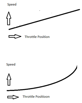
Let’s take, for example, the way that the cart would respond to the position of the throttle. Obviously, we want the cart to go from 0% of its maximum capable speed to 100% of it as the accelerator pedal goes from its “at rest” position to its “pedal to the metal” position. But just how the controller reacts to the accelerators movement is referred to as its “throttle response curve”. If we wanted an absolutely direct correlation, we would call that a linear throttle response. But let’s say you wanted to “ease” into taking off so you wanted the cart to react “gently” to the initial movement of the accelerator and then speed up more quickly with further motion. That would not be linear at all. If plotted on a graph of “accelerator motion versus speed of the cart”, it would have a different shape.
In the following drawing, the top chart shows a linear relationship (curve) between the position of the accelerator and the speed of the vehicle. In the bottom chart, the curve is altered to indicate that as the accelerator is first moved, the reaction of the cart in terms of speed, is quite “mild” compared to later in its travel. This might be referred to as a “logarithmic” curve, or by some other name (I’ve seen several) but the point is that it is no longer linear.
In order to “tell” the controller what curve you want, you have to “hook” the controller to some device that “speaks its language”. In the earlier days of the development of these kinds of controllers, one of the most common ways to do that was through a computer’s serial port (notebook or PC). As time went on, the method of communication shifted to using the USB port. Of course, you had to load a copy of the controller manufacturer’s special software on your computer, but that could usually be done quite easily by “downloading” from the manufacturer’s web over the internet. Some of the controllers had to be programmed with a special tool that only an authorized dealer could buy. So, you had to take the cart to an authorized dealer and let him set the options (for a fee, of course). This really opened up a whole new world in controller production. Some of the features that could be “programmed” on many of these controllers are as follows:
Throttle Response Curve (as mentioned above)
The controller can be programmed to accept throttle position information from different types of devices (potentiometer, inductive type, etc.)
The maximum speed that the cart can access can be limited (safety issue when kids are involved)
The maximum Current draw from battery pack can be limited
Making the cart run at only half-speed when in reverse can be selected or de-selected
The controller can be programmed to NOT run if the accelerator were to get stuck in a high-speed position when the cart was first told to move
Protection settings could be programmed to limit the controller to only operating if the battery pack voltage is safe for it to do so (so as to protect the controller from damage)
There are self-diagnostic features built into the software of most of these controllers that help identify problems with the system by flashing LEDs or using the back-up buzzer to signal what issues needed to be taken care of
Another reminder: we are still talking about the electronic controllers in SERIES type golf carts. Series meaning that the armature coils and the field coils in the motor are wired in series by the cart’s wiring system. Another type of system is called a “shunt” or “sepex” type. In a shunt system, the armature and the field each are controlled by separate outputs of the shunt controller. This gives the ability to manage current flow through the field independent of current flow through the armature. This makes for much better control of the system as we will discuss in future posts in this sequence. See you later, Ron.
In the last post of this sequence, we talked about carts using an electronic speed controller instead of resistors to control the speed of the motor. We discussed the technique that the motor speed controllers use to vary the voltage to the motor. The technique is called Pulse Width Modulation (PWM). In order to know how much modulation the controller needs to supply at any given time, it must have input from the driver of the cart. That is what we will talk about in this post. Where does it get this information from? Keep in mind that we are still talking about SERIES wired electric carts. We will get to the “shunt” or “sepex” type carts later.
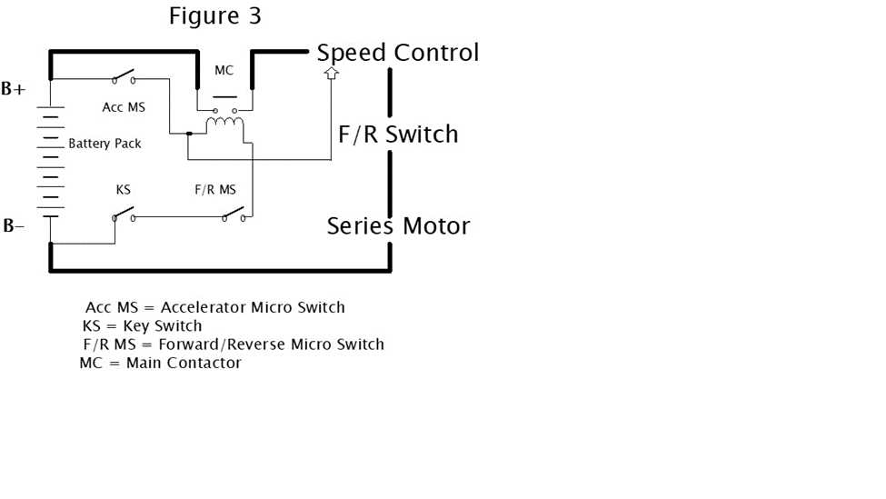
I copied the following diagram from a book that I wrote called Electric Golf Cart Repair 101 (and a half). There is a link at the bottom of this post if you are interested in information about the book. We’ll go through the need for each of the components in this post.
Toward the top and in the middle of the diagram is a thing referred to as the MC. As the ledger states, another name for the MC is the Main Contactor. It is actually what we have been calling the solenoid, so we’ll stick with that name. I always think of the solenoid as the “center” of operation of an electric golf cart. It is where two “worlds” meet. We’ll refer to the two worlds as the “low energy world” and the “high energy world”. The solenoid contains two circuits within itself. It consists of a coil circuit (low energy circuit) that when supplied with current creates a highly magnetic field. This magnetic field moves a “contact bar” internally that causes two contacts to short together (high energy circuit).
Notice that the wires to the coil side of the solenoid (lower part) are depicted on the diagram with smaller lines (smaller wires). That is because these wires carry (conduct) very little current compared to the larger wires depicted on the contact side (upper part) of the solenoid. It only takes a few milliamps of current through the coil of the solenoid to energize it (make it short the contacts on the high energy side together). That is very important because it allows us to use smaller wire and less “heavy” switches to perform what I call the “logic” switching. The logic (low energy) circuitry on our diagram includes the KS (Key Switch), the F/R MS (Forward/Reverse Microswitch) and the Acc MS (Accelerator Microswitch). Note that the F/R MS is a small switch that is activated when the regular F/R switch (the large one that you move with your hand) is moved into either forward or reverse. Until all three of these switches are activated (make closure), the cart can’t move because the battery pack isn’t connected to the high energy circuitry due to the unenergized solenoid. That is quite intentional and prevents the cart from moving before we want it to. Once the three switches are “happy”, the controller is ready to go. Notice that there is a small wire from the logic circuitry to the controller. It provides a “trigger” signal to the controller. The next diagram is of a typical older Club Car with an electronic speed controller.
Toward the top and to the right is the Motor Speed Controller. It is designated as “I” in the drawing. The parts that I want to talk about are the three connections to it in its upper lefthand corner. They are labeled pins 1, 2 and 3. Earlier I mentioned that when the three logic switches are activated in order to energize the solenoid, there was a “trigger” signal to the controller to let it know that the system was ready to go. That is it on pin 1. Pins 2 and 3 are where the throttle position sensor input comes into the controller. In the case of our example in the drawing, the signal comes from a device called a multi-step potentiometer. It looks from the outside just like the V-glide that was used in the model we talked about in the previous post, but instead of providing switching for the high energy circuitry, in this case it provides a low energy signal to the controller to tell it where the throttle is positioned at any given time. As I mentioned before, this input could come from a conventional potentiometer, or even an inductive device, depending on the design of the cart. Once again, for a detailed description of exactly how the system works, I recommend the book that is referenced at the end of this post. The controller uses the PW technology that we discussed in the last post to vary the bursts of energy (and therefore the average voltage) that are supplied to the motor. Thereby, the speed of the motor is varied without dissipating any energy by heating up resistors.
In our next post of this sequence, we will go into another type of motor speed controller. It will be the one that is used in “shunt” (sometimes called sepex) systems. They are significantly more complex but offer many advantages over the “series” type systems. See you next time, Ron.
In the last post of this sequence, we talked about carts that still used resistors to control the speed of the cart but didn’t have a solenoid and its circuitry for each resistor. It was a big improvement from the maintenance point of view over their predecessors. This month, we’ll talk about the next step in the evolution, which was to get rid of the energy consuming resistors altogether.
As we discussed in the first two posts of this series, the resistors slow the motor down by taking some of the energy that would be available to the motor and dissipating it in the form of heat. By controlling the voltage to the motor with an electronic speed controller, we eliminate using the energy to heat up the resistors. That means the battery pack will be able to supply the motor with energy for a longer period of time. There will, of course, be less time required on the charger and a longer range of driving time for the cart.
The method employed by the electronic controller to vary the voltage to the motor is called Pulse Width Modulation (PWM) and is a much more efficient method than heating up resistors. In the book Electronic Golf Cart Repair 101 (and a half), I spend a lot of time and effort to explain PWM in detail. If you really want to get into the nitty gritty of PWM, I highly recommend reading the book. Links to Amazon, where the book can be purchased, is at the bottom of this post. But for now, we’ll talk in general terms to get a picture of how PWM works.
Let’s say we had our golf cart motor connected directly to the battery pack (36 volts). No resistors, motor controller or anything else in the circuit. Just as soon as the circuit was made complete, the motor would begin to spin. It would continue to gain speed, right up toward its top speed. The top speed would only be limited to the design of the motor and how fast it is rated to go at the 36 volts by design. How much current it required to maintain the top speed would, of course, be proportional to the load (how much the cart weighs, how much the driver weighs, how level is the terrain, etc.)
But now let’s pretend that we placed a toggle switch in the circuit to where we could turn the motor on or off with a flip of the switch. Now remember, that this is just an imaginary experiment. If you tried to do this in “real life”, it would be a disaster for the motor, the battery pack, the switch and certainly for the driver of the cart.
As the switch is first turned to the on position, the cart would lunge forward as the motor starts to speed up toward top speed. Then as the switch is turned off, the cart would start to coast to a stand-still.
Now, let’s say that we decided to turn the switch on for one second and then off for one second and repeat the process for several seconds. The cart would lunge forward trying to reach top speed but before it ever got there, the switch would be turned off and the cart would start to coast. In the first two second period of time, the voltage to the motor would average 18 volts (36 volts for one second and 0 volts for one second) even though 18 volts was never sustained for any length of time. The average speed of the cart would be something that depended on the load, the specifications of the motor, etc. but it would be somewhere between zero and whatever the top speed of the cart was designed to be. As the process is repeated, the cart would finally (after getting over its initial attempt to get going) average out to some speed, even though it never really sustained any specific speed for any length of time.
But now, let’s say that we could flip the switch back and forth several times a second. Now the travel of the cart would smooth out a bit, in that it never was in one position long enough to get toward 0 or full speed. If we kept the switch in the on position twice as long as in the off position for a certain period of time, we would speed up the cart by increasing the average voltage to the motor during that period. Well, that is what an electronic speed controller does. It pulses the motor with bursts of energy proportional to the speed desired by the cart’s driver. The faster the driver wants to go, the wider the pulses of voltage to the motor are (pulse width). With the motor speed controller, this switching or pulsing happens at a rate of around 12 thousand times per second, so there is no noticeable lunging of the cart. It reacts to the average of the voltage to the motor for any given period of time. That is how pulse width modulation works. Now, of course, the controller must have some important information from the driver in order to determine just how wide to make its pulses of energy to the motor, and that is what we will discuss in our next post in the continuation of the study of electric golf cart evolution. See you then, Ron.
In order to get rid of most of the solenoids, but still be able to utilize the resistors for motor speed control, Club Car came up with a configuration called the V-glide (by most people). It was a big improvement over the previous system in terms of maintenance. The following is a diagram of a V-glide model taken from the book referenced at the bottom of the post (Electric Golf Cart Repair 101 (and a half).
–
As you can see from the drawing, the resistors are still used in the circuit, but they are “added in” or “taken out” by the use of some contacts and a “wiper” in the device called the V-glide. The way that the contacts and their wiper are packaged, the unit looks like a “wedge”. Its placement in the golf cart is in front of the batteries just to the driver’s side, mounted to the frame near the bottom of the cart. You can see the large wires (6 gauge) connected to the back of the V-glide and the accelerator linkage on the front (toward the driver’s side). The wiper inside of the V-glide moves from contact to contact with the advancement of the accelerator. E-Z-Go had a similar model that is shown below (the drawing is taken from the same book):
Both systems use a solenoid to activate what I call the high energy circuitry used to drive the motor. The logic switches used to energize the solenoid are what I call the low energy circuitry. The solenoid (or what is called the Main Contactor in the drawings) is where the low energy circuit and the high energy circuit meet. The low energy circuitry allows us to use small wiring and low power-rated switches (like microswitches) in order to energize the solenoid. Once energized, the solenoid’s high energy contacts can withstand the current flow needed to drive the motor. There is a remarkably high surge of current when the motor first tries to get up to speed from a stopped (stalled) position, and the solenoid is designed to handle it. The rest of the contacts in the V-glide of the Club Car and on the speed control board of the E-Z-Go are only designed to withstand incremental increases in the current supplied to the motor as the accelerator is moved to the faster position. They are not designed to be the “first contact” made when the initial surge happens. Only the solenoid is “tough” enough to do that.
Typically, on all golf carts, it takes three things to happen on the low energy side of the solenoid to allow it to energize. It takes the key switch being turned on, the forward/reverse microswitch to be activated and the accelerator switch to be activated. These things prevent the cart from taking off until the driver is ready to go. In troubleshooting a cart that won’t run, the technician’s first job is to isolate the problem to either the low energy side of the solenoid or the high energy side. A good meter can be used to see if the proper voltages are where they need to be to energize the solenoid and whether the solenoid is actually working when it is energized. If the low energy circuitry is all in order and the solenoid is good, then it is time for the technician to start working his way through the high energy side to find the culprit that is keeping the cart from running.
In the next post in this series, we will take a look at a golf cart with an actual “active” motor speed controller. By this, I mean an “electronic box” that allows for speed control without the use of the big resistors. The resistors (as I mentioned in the last post) are a very effective way to control the speed of the motor, but they use bunches of energy. They simply dissipate the energy that the motor isn’t getting (when they are in the circuit) in the form of heat. The electronic controller, on the other hand, just affects the supply of voltage to the motor through a technique called Pulse Width Modulation (PWM). In the book that I reference at the bottom of this post, I spent a bunch of time explaining PWM in detail, but in the next post we will talk about it in general terms, so that it will be easy to get the idea of how it works without getting hung up in a bunch of “techy” terms. See you next time, Ron.
For information about books written by Ron Staley about both electric and gas driven golf carts and their repair, visit the following links.
Electric Golf Cart Repair, both as an eBook and in Hardcopy:
This post is the first of several on the subject of the evolution of electric golf carts.
According to Wikipedia, it was in the early 1930’s when it all began. A guy named JK Wadely noticed the convenience offered by a three-wheel electric cart that had actually been designed for helping somebody disabled get around a grocery store (and other non-golf related places). He decided to try it out on a golf course and found it rather UNSUITABLE for such terrain, but decided things could be “adjusted” to make something “kind of like it” that would work very well for the purpose. The idea caught on, but it wasn’t until the 1950’s that Merle Williams began production of the Marketeer electric golf cart in Long Beach, California. Through the years, many other manufacturers jumped in and started producing electric golf carts also.
The early carts all had some things in common, like using batteries, and DC motors, but they came up with several variations of how to control the speed of the vehicle. The batteries were usually lead acid batteries, just like the industry has used for years and years. They are quickly being phased out by the later technology of lithium-ion batteries, but the lead acid batteries have truly been the standard for the golf cart industry for many years. In order to understand speed control, we need to take a look at how DC motors work.
The common method of using a DC motor in a golf cart for many years was called a “series” wiring configuration. The rotation of the shaft of the motor depends on magnetic fields opposing each other within the motor, between the field coil (attached to the housing of the motor) and the armature coil (attached to the rotating shaft). These magnetic fields are the result of the cart’s batteries being wired in such a fashion that current can flow through both of these coils in a single circuit. The more current that flows through the coils, the stronger the opposition is that occurs between these coils and, therefore the speed of the shaft is increased. In order to control the speed of the motor, we need to be able to control the amount of current that is available to the series wired coils. As a matter of fact, for many years, the main difference between models of golf carts was primarily in how they controlled that amount of current.
I don’t want to get too “mathy” in this post but it is important to know that the amount of power (in watts) that a motor can produce is limited to the strength of the source supplied to it (in volts) multiplied by the amount of current (in amps) that is available. In other words, Power (in watts) is equal to volts supplied (E) times the current (I) that is available or P = I x E. So, in order to reduce the power that the motor produces, we have to control either the E (voltage) to it or the amount of current (I) that is available.
One of the ways that was used in some of the early carts was that of switching more or less batteries into the source to the motor. In most carts, there were a total of six (six volt) batteries wired in a series configuration to achieve a maximum potential of thirty-six volts that could be connected to the motor at one time. But you could use heavy duty switches or solenoids to remove some of the batteries from the motor’s supply to slow the motor down and switch them back into the circuit to speed things back up again. The technique came, however, with its problems. After driving the cart a reasonable distance, you had a battery pack with batteries that were unevenly discharged. Depending on what speed the cart had been driven at most of the ride, some batteries would be used more than others, resulting in an unevenly discharged pack. The charger wasn’t smart enough (or designed) to know which ones to give extra charge back to in the charging process, so the battery pack was constantly unevenly charged. This resulted in a much shorter life expectancy for the pack. In all the years that I worked on carts, I only ran across a couple with this type of speed control system, so I won’t bother you with a wiring diagram of one. Instead, we’ll turn to the next method of reducing the voltage and the current to the motor that was quite common for many years. It was accomplished by adding a variable amount of resistance in series with the motor. In order to discuss the system, I have copied one of the drawings from a book I wrote about golf cart repair. The drawing shows a typical method of how the resistance was added and removed. This diagram is of an early Club Car cart that used what was referred to as a resistor system:
For the purposes of this post, we won’t go into a detailed description of exactly how it all works, but the point is that when the accelerator is advanced (once the key switch and the F/R microswitch are activated), the resistors are placed in series with the motor to keep its seed down. The maximum current through any circuit is equal to the voltage applied to the circuit divided by the resistance offered by the circuit (I = E / R). So, as there is more and more resistance added to the circuit, the current through the motor is decreased (thereby slowing its rotation down). When the accelerator, that is linked to a series of switches, is moved it activates switches, that in turn, control solenoids to remove resistors from the motor’s circuitry. The resistors (if you ever look under the seat of one of these carts) are big coils of wire that not only provide resistance of the circuitry, but are large enough physically to be able to dissipate the heat that is produced in the process. The main disadvantage of this type of system is that in the process of slowing the motor’s rotation, much energy is consumed (dissipated as heat) by the resistors. That limits the range of the battery pack. Of course, all that energy must be replenished in the batteries’ charging process. Another problem is that with five solenoids at work, there is definitely room for much more failure due to wear and tear on them. Golf cart solenoids ae a special “breed’ of solenoid. They are what is called a “constant use” solenoid. Unlike an automotive solenoid, which is only used in the starter circuit long enough to get the engine started and then is disconnected, these solenoids must withstand being used in their circuitry for long periods of time. For a detailed discussion of the operation of this type of system, I recommend the book I wrote called Electric Golf Cart Repair 101 (and a half). The link at the bottom of this post will get you more information about the book.
In our next post in this sequence, we will look at a couple of models (one Club Car and one E-Z-Go model) that still used resistors but worked with only one solenoid (less maintenance). The basic operation is still the same, but the switching “in and out” of the resistors is simplified and made a whole bunch more reliable. See you next time, Ron.
For information about books written by Ron Staley about both electric and gas driven golf carts and their repair, visit the following links.
Electric Golf Cart Repair, both as an eBook and in Hardcopy:
Many E-Z-Go owners have experienced hearing a grinding noise at the rear end of the cart when trying to take off. A cart with this symptom will usually either not move or will only lunge a bit but won’t make it very far. This symptom is caused when there is a problem with one of the rear hubs. E-Z-Go’s design is a little different than many others in that they use a hub and drum combination. The part is attached to the axle with a set of splines that mate with spines on the end of the axle. The hub/drum is secured to the end of the axle with a castle nut that is usually covered with a dust cover.
To see if a hub is the problem with the noise and non-movement, you can just take the rear hubcaps off and remove the dust covers and try to move the cart with the motor (engine). While depressing the accelerator, watch the castle nuts. If a hub has the problem that we are speaking of, you will see the castle nut moving, even though the wheel isn’t spinning. The differential, of course, tries to transfer the torque of the motor to the easiest side to move, so the spinning axle side will be quite obvious. The hub/drum is always what stripes out, it is hardly ever the splines on the axle.
The hub/drum is easily replaced, however, there are a couple of things to remember to do the job right. To replace the hub/drum, you simply remove the dust cover and then the castle nut and pull the unit off of the end of the axle. There is a cotter key through the castle nut that must be removed to get the castle nut off. Once the hub/nut is removed, it is VERY important to clean the remaining splines on the end of the axle. If you don’t, the metal shavings and debris that is left in the splines will get compacted into the area where the hub bottoms out against the outer axle bearing assembly. If that happens, when installing the new hub/drum, even though the castle nut is tightened, with rotation of the axle and vibration etc. the debris will eventually work its way out and there will be additional space “developed” (where the debris was) that will result in a loose castle nut. I go to the trouble of taking a small “pick” of some sorts and running up and down each spline on the axle several times to clean the stuff out of there. After that, I use some parts cleaner to wash everything out. I then put a small amount grease on the spline and slide the new hub/nut onto the axle. It is very important to tighten the castle nut to the right torque. The documentation that I have seen says that it should be tightened between 90 and 140 ft. lbs. That is pretty darned tight. You really should have a torque wrench to do it right. I bring the torque up to about 100 ft. lbs. and then continue tightening it until the next hole in in the axle that accommodates the cotter key lines up with a slot in the castle nut. That way I know it is just over 100 ft. lbs. and that always works just fine. If the castle nut isn’t tightened enough, there will be some slight movement of the hub on the axle and it will strip the splines on the new hub/drum in no time at all.
For information about books written by Ron Staley about both electric and gas driven golf carts and their repair, visit the following links.
Electric Golf Cart Repair, both as an eBook and in Hardcopy:
A recent comment that I received reminded me that I had never really discussed how to test for a bad battery in a gas golf cart. I go into a lengthy discussion of battery testing in the “Electric Cart Stuff” section, but there is nothing there about a gas cart’s battery. So, here it is.
First off, it is important to understand that the battery used in a gas golf cart is a totally different “critter” than the one used in an electric cart (or at least it is supposed to be). The battery in the gas cart is more like a battery used in an automobile. It is a 12 volt (we’ll get into that in more detail in just a moment) and it relies on Cold Cranking Amperage (CCA) to have enough energy to spin the engine over long enough to get it started. Once the engine is started, the battery has done its job and the rest is up to the starter/generator (S/G). The S/G supplies a charge voltage, controlled by the voltage regulator (VR) to recharge the battery as the engine runs. The battery, at that point, acts as what I call a ballast. It can still supply short term energy to anything that might require more than the S/G can handle for short periods of time, but basically it just sits there RECEIVING energy from the charging system to maintain its proper charge. It is not intended (like electric cart’s battery) to supply a constant source of energy for anything for a long period of time.
Let’s talk about a “so called” 12-volt battery. Batteries are made up by connecting (within the battery package) what we call 2-volt cells in series, to add up to the total battery’s rated voltage. In our case, it takes three 2-volt cells connected in series to add up to the 12 volt rating of the battery.
However, a 2-volt cell really isn’t a 2-volt cell while it is usable. A 2-volt cell, when fully charged, ideally measures about 2.15 volts. By the time it has discharged down to 2 volts, it is nearly useless, and needs to be recharged. So, our 12-volt battery, being made up of three 2-volt cells should measure about 12.9 volts when properly charged. That is (in battery language) a far cry from 12 volts.
So, if your S/G and VR are doing their jobs, when you walk up to the golf cart, lift the seat and put a meter across your battery, it should measure about 12.9 volts. As the battery ages, its ability to come back up to a full charge lessens, so if your battery has a few years on it, you might measure closer to 12.75 or so, but should be considerably higher than 12 volts.
Now the question comes up: what happens to the voltage of the battery when you hit the accelerator to start the engine? Answering that question is an excellent way to “load test” the battery. Leave the meter across the battery and watch it as you try to start the engine. Under no circumstances should the voltage drop below around 11 volts while starting the engine. For an older battery, it might still work if it goes as low as 10.5 volts, but it should never go any lower than that. Of course, as soon as the engine fires, the generator function of the S/G should kick in under the supervision of the VR and start recharging the battery, so you should see the voltage at the battery crawl back up to the 12.9 volts right away and then go on up higher as the RPM of the engine increases. Ideally, the VR will limit the maximum charging voltage to about 14.5 volts to prevent damage to the battery.
So that is what you should see going on with your meter during the “start-up” process. What could possibly go wrong? Lots of stuff.
Let’s say that when you lift the seat and do your test with nothing turned on, and the cart is just sitting there, I call this the “static” test of the battery. Let’s say that it only reads 11.6 volts. What we don’t know is “why” at this point. It could be that the battery is bad or that the S/G and VR aren’t recharging it. The best thing to do is to put an automotive charger on the battery overnight and then test it again. If it is up around 12.9 volts, then we will be suspicious of the S/G or VR, but we haven’t proven anything yet. If the static voltage isn’t around 12.9 after the overnight charge, then the battery simply won’t accept a charge and needs to be replaced (assuming the charger is known to be good). The next part of the test is what I call the “dynamic” test where we continue to monitor the meter while we actually try to start the engine. If the voltage doesn’t drop below 11 volts and the engine starts, we will even be MORE suspicious of the S/G and VR. If the voltage drops way below the 11 volts (let’s say 8 volts) then we are back to the battery again. It is quite common for the static volage to come up to something fairly normal after an overnight charge, but the battery doesn’t have the “capacity” to supply the necessary energy for the start-up without dropping the voltage too low to make things work.
So what have we done?
By doing the overnight charge, we have given the battery an opportunity to become properly charged, in case the problem is that the S/G or VR is the problem.
By seeing what happens with the dynamic test, we are doing a GREAT load test of the battery. You can buy a load tester at an automotive supply store, but it isn’t the same as using the actual cart for the test. The cart IS the proper load that the battery should be tested with. A load tester generally only loads the battery to about a 100 amp load. When starting the cart, we can easily exceed that amount. Most of the gas cart’s batteries are rated at least 400 amps CCA, so the external load tester may not test under enough of a load or for long enough to make a good discission about the condition of the battery. Using the cart as our load tester is a far superior method than an external load tester.
If we determine that the problem is the S/G or the VR, then we need to do some procedures to isolate further. Those procedures are described in another page of this website called “E-Z-Go gas cart Starter/Generator and Voltage Regulator” under Gas Cart Stuff in the drop-down menus (E-Z-Go gas cart Starter/Generator and Voltage Regulator – Welcome to Golf Cart Stuff Hodgepodge). Don’t worry about the E-Z-Go part. The procedure is basically the same for all makes and models.
For information about books written by Ron Staley about both electric and gas driven golf carts and their repair, visit the following links.
Electric Golf Cart Repair, both as an eBook and in Hardcopy:
In the old days, most people just wired the lights up on a golf cart similar to the diagram below:
Because the 36-volt cart consisted of 6 6-volt batteries strung in series, it was easy to “steal” 12 volts (that’s what most golf cart lights are designed to use) by just connecting up to 2 of the batteries in in the chain of batteries. That is what is indicated by the diagram above. For instance, you could go from the negative post on A battery in the pack to the positive post on the B battery and bingo, you’ve got 12 volts (6 volts per battery). You could, likewise, go from the negative post of the B battery to the positive post on the C battery, and get the same thing (12 volts). It really didn’t matter which “pair” of batteries you pick, as indicated by the drawing.
Of course, you had to remember to turn the light switch OFF after using the lights, or the 2 batteries that were being used for the lights would be drained from the load of the lights. So, someone came up with the idea to make it so that when you shut the key switch off, the lights would automatically turn off, even if you left the light switch on. They accomplished it by the use of a simple and inexpensive device called a relay.
The drawing above represents a typical relay. Notice that it is made up of 2 basic elements: a coil and a set of contacts. The idea is that when the coil is “energized”, the contacts are “pulled” together to provide current flow through a circuit (in this case the cart’s lighting system).
The numbers that I have placed by the terminals of the relay are a standardized set of numbers dictated by an electrical engineering group that defines such things. So, we can see that terminals 85 and 86 are the terminals that need to have a voltage placed across them in order to energize the relay and terminals 30 and 87 are the terminals that will “make” or “break” in order to turn the lights on or off.
Both the coil and the contacts of the relay have “ratings” that need to be observed when placing them in a circuit. The most common light relay for a golf cart will say something like 12V 30A on them. By this, they mean that the coil voltage of the relay is 12 volts. That is what it takes to properly energize the relay. The 30A part means that once the relay is energized, the contacts can withstand a current flow through them of up to 30 amps. The 30A has nothing to do with the current that it takes to energize the coil. It only takes a few milliamps to do that. And, the lights will take much less than 30 amps to operate. The old fashioned incandescent type lights would usually “draw” closer to 10 to 15 amps, and the newer LED type will only draw a couple of amps. So, the 12V 30A relay is more than tough enough to do the job. So, here is a typical circuit that includes a relay to shut the lights off when the key switch is turned off:
The circuitry of the lights themselves is basically the same as it was. It’s just the manner in which the energy to them that is supplied to them that is modified. Instead of the positive end of the 12-volt supply (no matter which 2 batteries are selected to provide it) going directly to the light switch, it only gets connected to the switch when the relay is energized and that only happens when the key switch is in the “on” position.
As you can see from the drawing, the B+ post of the battery has a unique role. It provides 36 volts to the logic switches because their other side goes to B-. However, it supplies 12 volts to the relay because its other side goes to the negative post of the next battery (not B-).
Now, the above illustration only works when the key switch provides B+ to the logic switches mentioned in the first diagram. However, there are models in which the B+ is always applied to the logic switches and the key switch provides B- instead. In that situation, the relay is connected as shown below:
In this case, the key switch is used to provide B- to the solenoid instead of B+.
Of course, there are dozens of different configurations for golf cart lighting systems but the purpose of this article is simply to help someone who has never worked with relays before, understand what they are for. They can use the energy in one circuit (in this case the logic switching circuit) to control the energy in another circuit (in this case the light system) to make or break its path (provide switching). Relays are often used for other “appliances” that are added to golf carts also (like radios for instance).
Another important thing about a relay is that because the current required to energize its coil is very small (compared to the current that the appliance itself actually uses) the switching voltage for the coil can use much smaller and easier to run wiring. Let’s say, for instance, that you wanted to add a horn to your golf cart. Horns usually draw quite a bit of current, perhaps as much as 15 amps. Now granted, the horn is usually only used in short “bursts” so the wiring doesn’t have much time to overheat, but the wiring still needs to be in the range of 12 or 14 gauge or so. By using a relay, the heavy wire that supplies the energy to the horn can go directly from the source of current (the batteries) to the horn through the contacts of the relay, but the switching can be controlled by a relay whose coil circuitry needs only to use perhaps 18- gauge wiring or so. It would look like this:
In this case, we aren’t concerned with the key switch at all. We are just making it so that we can run a nice manageable size wire to wherever we want the switch to be located but still have an adequately sized size to supply the relatively large amount of current that the horn requires.
Relays are very useful devices. They are often used in HVAC (air conditioning and heating) work to control huge amounts of current (like for compressors or heating elements) with very small voltages used for switching (like a thermostat would use). Maybe this will clear things up a little about why relays are used and how they are wired. Ron.
For information about books written by Ron Staley about both electric and gas driven golf carts and their repair, visit the following links.
Electric Golf Cart Repair, both as an eBook and in Hardcopy:
In a book that I wrote about golf cart repair, “Electric Golf Cart Repair 101 (and a half)”, I began the first chapter with a statement that a “Meter is a Must”. That book was written with the “do it yourself” mechanic in mind and the statement was certainly true. However, even if you never intend to repair your golf cart (beyond the very simplest of situations), there are some very interesting things that can be learned about the condition of the cart with a simple test or two with a very inexpensive meter. You don’t need to be an electronics genius or even very mechanically inclined to have some fun with a meter and get a feel for what is going on with things. By far and away, the most important thing that you can take a look at is the condition of the batteries, but there are some other things you can do with a meter that will be helpful also, so let’s take a look at a meter and see what it is all about.
In the process of working on golf carts for people over a period of years, I was surprised to see how many people seemed intimidated at the mention of using a meter. In many cases, I could have told the customer what was wrong with their cart as well as what needed to be done about it over the phone, if I could have just gotten them to make a simple meter reading and tell me what they saw. It was as if the mere mention of a meter separated our worlds from one another.
Because using a meter to take simple readings on a golf cart is so easy, and because purchasing a meter is so inexpensive, I decided to write this article to shed some light on it, even for the least experienced “would be” meter reader. Keep in mind that this article is NOT about how to use a meter in EVERY imaginable situation regarding golf cart repair. Rather, it is intended only to give you the very basics of how to use a meter to make a DC voltage reading and to provide a couple of practical examples of using the meter while working on a golf cart. To learn more about what can go wrong with a golf cart and how to troubleshoot one, I recommend the book “Electric Golf Cart Repair 101 (and a half)” which is available from Amazon at this link: Book: Ronald L Staley: 9780578560557: Amazon.com: Books
In “the old days”, meters were mostly “analog” meters. That meant that they had a needle that moved over the printed scales of the face of the meter. Each scale selection of the meter had its own representative markings on the face of the meter, and the operator had to be careful to be sure that the markings he was using for his reading were the correct ones. It could get very confusing for a beginner or even a veteran meter reader. Thank goodness, most all of the newer meters are “digital” and simply show the numbers that represent the reading on an “easy to read” display. The meters are usually referred to as “DMMs”, which stands for Digital-Multi-Meter. The “multi” part indicates that the meter can be used for more than just DC voltage readings (like the ones we are going to use it for). They can usually also read AC voltages, resistance in ohms, current flow in amperes, etc., but we don’t need any of that to do the simple tests we are going to be talking about in this article.
So, let’s take a look at just what a modern day, inexpensive meter looks like. In the book I wrote (as mentioned above) I used a very inexpensive meter as an example. The meter came from Harbor Freight (HF) and was a model 90899. Then I discovered that I had another meter just like the 90899, but it had a number of 98025. The only difference I could see was that the power switch was yellow instead of red. So, apparently, they “play” with the identification numbers some from time to time, but just so it does the job, it’s OK. I just went to Harbor Freight to see what is their current “cheapo” meter is and sure enough, it was still the same meter and even still had the 90899 as an identification number on it. Its price had gone up from about $5 in 2019 to about $10 now, but if you learn how to use it, it will be the best 10 bucks you ever spent on your golf cart. Now, if you are fortunate enough to have a nicer more expensive meter, that’s even better, but it will still work roughly the same way. The readings might be a little more accurate with a more expensive meter, but that is not necessary for what we are going to do with the meter in this article. Most of the time, I use a fairly expensive “Fluke” meter when I am troubleshooting, but that is just because I have it and it’s convenient. The HF meter will do just about anything the Fluke will do. It may be a little less accurate and a little slower to take a reading with, but it will suffice.
The HR 90899 looks like this:
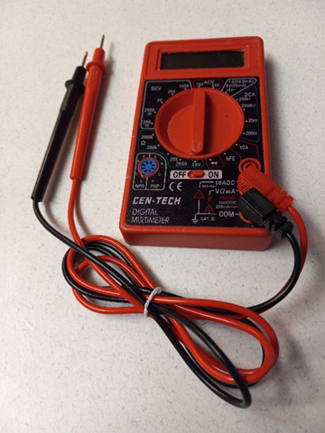
We’ll now go through what you need to do to use it. The meter comes with two leads (probes). One is black and the other is red. The black one needs to be plugged into a “hole” at the bottom right of the meter. The correct hole is labeled “COM”, which stands for common. For all of our “basic tests”, that’s where the black probe will stay connected. If you are using some other brand of meter, there will still be a place for the black lead. It might be labeled in some other way (“negative”, or “-“ or something else), but you will figure it out. The red lead will go into the hole just above the “COM” hole. It is used for voltage tests (V), ohm tests (Ω), and low value current (mA) tests, which cover all that we will be using in our basic testing. The hole is labeled V Ω ma. Once again, if you are using some other brand of meter, the hole might be labeled in some other way (“+”, “positive” etc.), but you want the hole that is for taking positive DC voltage readings. Our meter now, with the leads plugged in, looks like this:
All of the tests that we are going to do in this part of the article, will be “voltage” tests. So, the next thing we need to do is to get the meter turned on and the right “scale” selected. The reason there are so many scales that can be selected, is to make the readings more accurate. If you measure a very low voltage on a very high scale, the reading’s accuracy is drastically affected. You would still get a “ballpark” reading, but it won’t be as good as it would be, if a lower scale had been selected. Meters of all kinds, even the old “non-digital” type with the needle that moves across the front of the meter with a reading, tended to get better readings when used at nearly full scale. And these newer “digital” meters are the same way. In our case, the highest voltage we would ever need to test would be that of the entire battery back. Depending on the model of cart you have, that would either be 36, or 48 volts. On this particular meter, the scales for DC readings jump from 20 to 200, so I must pick the higher one of 200. That means that this scale should never be used to test for a voltage higher than 200 volts. We don’t have to worry about that with our golf cart. However, it would be better if we had for instance a 60 or even 100-volt scale, but we don’t, so we will have to settle for the 200-volt scale. Having worked on these things for many years, I can assure you that the meter will be accurate enough for our purposes on the 200-volt scale, so don’t worry about it.
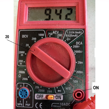
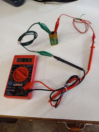
So, to kind of get the “hang of it”, we’ll set the meter up to measure the voltage of a 9-volt battery. First, we need to turn the meter “ON”.
I’ve pointed out the “ON” switch for this particular meter in the picture above.
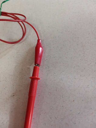
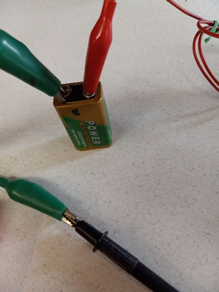
Next, we need to select the proper “function” and “scale”. In our case, as discussed above, we will be measuring DC voltages (direct current) and we want to select the lowest scale for the range of voltages we think that we are going to observe. Since we are going to measure a 9-volt battery, we will select the 20 DCV scale. In the picture above, I’ve pointed out how that will look. Of course, it would be nice if the meter had a 10-volt scale, because then we would be measuring closer to “full scale” and thereby ensure better accuracy, but in our case, our “cheapo” meter only has a few scales, so we will pick the one that is closest to the approximately 9 volts that we expect to measure, and that is the 20-volt scale (20 DCV). Notice in the picture that there is a small “dot” on the end of the “pointer” that is rotated to make the function and scale selection. That is important, because if you have the other end of the pointer aimed at 20 instead of the “dot” end, it won’t work. Next, we need to attach the leads with the probes on the connectors of the battery. You could just hold the probes on the terminals by hand, but it is very hard to keep them there while you are making a reading, so, I recommend the use of some jumpers that have “alligator clips” on their ends. You’ll see in the next pictures, that I have simply connected one end of the jumpers to the end of the probes and the other ends to the point where the test is to be made:
On the side of the 9-volt battery, there is “-“ and a “+” to indicate the negative and positive connectors. Of course, the black one will go on the “-“ and the red one will go on the “+”.
One of the first things you will notice is that when you first connect the meter to the battery, the meter will appear to go “nuts” for just a second. You need to let it settle out for a second or so until you get a steady reading. This has to do with what is called the meter’s “sampling rate”. The meter is actually looking at the voltage of the battery every few milliseconds and then displaying an average of what it sees on the display. This is where a more expensive meter has somewhat of an advantage. It will have a much faster sampling rate and therefore come to a stable display much quicker. But that is no “big deal”. Just be patient with the “cheapo” meter and give it a chance to settle out before you trust its reading.
As indicated by the pictures, if the 9-volt battery is good, the meter should show something above 9 volts, like 9.42 or so.
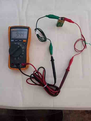
Just for a comparison, I hooked up the Fluke 115 that I used to the same test situation below:
As you see, everything is still the same: a red lead connected to the positive of the battery and a black lead connected to the negative connector of the battery. The Fluke reads about a hundredth of a volt higher than the “cheapo” meter, but for what we are doing, we are certainly not going to worry about a few hundredths of a volt one way or the other.
We are about to use the meter to do some testing on a golf cart, but before we do, we need to figure out what kind of readings we should expect to see.
This leads to another discussion that we need to understand about batteries if we are going to understand the readings that we get from them in a golf cart. A 6-volt battery really isn’t a 6-volt battery at all. Neither is an 8-volt really an 8-volt battery. Neither is a 12-volt battery really a 12-volt battery (at least most of the time). Notice our good 9-volt battery didn’t read 9 volts. It read around 9.4 volts. That may not sound like much difference, but I hope to convince you that it really is.
Golf cart batteries are actually constructed by placing 2-volt “cells” in series. This is a cone inside the packaging of the battery, so you can’t see it, but that is what is done. Likewise, a 2-volt cell isn’t really a 2-volt cell (when it is charged to its maximum). When properly charged, a 2-volt cell will (under ideal circumstances) read around 2.15 volts. By the time it is discharged down to 2 volts, it is almost totally “dead”. So, if we connect 3 “2-volt” cells in series, to produce a 6-volt golf cart battery, when properly charged, it should read around 6.45 volts. As the battery ages, it doesn’t charge back up to quite as high a charge state, so we usually expect to see a fully charged 6-volt golf cart battery read around 6.33 volts or so. That means that if we have 6 of them in series to create a 36-volt cart, fully charged the “battery pack” as a whole, should read around 37.9 volts, NOT 36 volts.
Likewise, a 48-volt cart, when fully charged should read about 50.64 volts. If it has 6 8-volt batteries, that’s 2.11 volts per cell multiplied by 4 cells per battery multiplied by 6 batteries (2.11 x 4 x 6 = 50.64). If it has 4 12-volt batteries in it, that’s 2.11 volts per cell multiplied by 6 cells per battery multiplied by 4 batteries (2.11 x 6 x 4 = 50.64).
The following chart is something that I put together and represents what most golf cart manufacturers characterize as the charge to discharge cycle of the batteries as the golf cart is used. The information varies somewhat from manufacturer to manufacturer, but I have sort of averaged their information out to get an overall picture of how it works.
State of Charge
One Cell
6-volt (36-volt pack)
8-volt (48-volt pack)
12-volt (48-volt pack)
100%
2.1 and over
6.3 (37.8) and over
8.4 (50.4) and over
12.6 (50.4) and over
90%
2.08
6.24 (37.44)
8.32 (49.92)
12.48 (49.92)
80%
2.07
6.21 (37.26)
8.28 (49.68)
12.42 (49.68)
70%
2.05
6.15 (36.9)
8.2 (49.2)
12.3 (49.2)
60%
2.03
6.09 (36.54)
8.12 (48.72)
12.18 (48.72)
50%
2.01
6.03 (36.18)
8.04 (48.24)
12.06 (48.24)
40%
1.98
5.94 (35.64)
7.92 (47.52)
11.88 (47.52)
30%
1.95
5.85 (35.1)
7.8 (46.8)
11.7 (46.8)
20%
1.93
5.79 (34.74)
7.72 (46.32))
11.58 (46.32)
10%
1.88
5.64(33.84)
7.52 (45.12)
11.28 (45.12)
0%
1.75
5.25 (31.5)
7 (42)
10.5 (42)
If we start at the top on the left side, the term “state of charge” is used to describe how much usable energy is actually left in the battery at any given time. Obviously, when fully charged, the battery is said to be at a 100% state of charge. But what happens when the battery is used is kind of interesting. If you look at the column that represents a 36-volt cart with 6 6-volt batteries in it, you can see that the battery doesn’t go from 6.3 volts at 100% down to 0 volts at 0%. Notatall! In its whole cycle of discharging, it only goes from 6.3 down to 5.25. And that would be taking the charge level of the battery clear down to 0%. Most manufacturers recommend that you never go below the 50% charge state, which is about 6 volts. So, you are really working with from 6.3 (or just a little higher) down to 6 volts as the entire variation in the battery’s voltage over a normal charge-discharge cycle. In some support literature from battery manufacturers that I have read, they say not to go lower than 50 to 80%, but from experience, I can tell you that taking the batteries down lower than 50% shortens the lifespan of the batteries drastically.
Since we are dealing with such small differences in voltage representing such large variations in state of charge, the DMM is a much better tool than one of the old analog meters. It was hard to detect such small differences with the needle above the markings on the display. Just a “needle’s width” of movement might indicate the whole difference between two different readings. Thank goodness for DMMs.
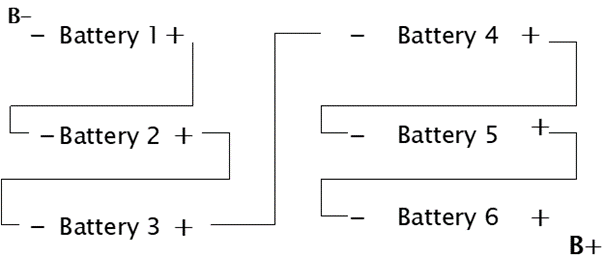
So let’s get practical and start doing some reading on a “hypothetical” golf cart. The first thing we will look at is the voltage across the whole battery pack. Since the golf cart batteries are “hooked” in series, we have to determine where they “start’ and where they “end”. Here is a drawing of 6 6-volt batteries hooked in series to form a 36-volt pack:
The way that the batteries are placed in the cart’s battery box varies from model to model. Battery 1 could be anywhere (physically) in the box, and therefore, so could Battery 6 and everything in between. Their placement is made to accommodate the shape of the box and the series string could start and end anywhere. You have to figure out how it is arranged on each cart you are going to make measurements on.
Our intention is to take a reading with our DMM “across” the entire pack. That means that our negative probe will be connected to the spot marked B- in the drawing. Notice, that is the negative post of what is called “Battery 1” in the drawing. Then, with our positive probe, we want to connect to the spot marked B+ on the drawing. Here is where the “jumpers” that I mentioned earlier will come in handy. It’s very difficult to hold two probes on two different places at the same time and get a reading. Plus, lots of times the probes want to “slide around” while you are waiting for the reading to “settle” out, as I mentioned earlier. Often times, I will clip the negative probe to B- (using the jumper with the alligator clips on it) and just use the positive probe to look around for readings. Most of the time (not always), the readings will be made with the negative probe on B-, so I just clip it on to B- and leave it there.
In order to locate B- and B+, you will notice that there are “large” wires and “smaller” wires connected to various places in the battery compartment. The larger wires are usually either 6 or 4-gauge wires and are connected between the batteries to form the series circuit. These larger wires also connect the batteries to other major components in order to supply the large amount of current required from the batteries to run the motor and propel the cart. So, first off, we want to connect our B- probe (preferably with the jumper with the alligator clips) to B-.
As indicated by the diagram, the batteries are wired in series, starting with Battey 1. The negative post on Battery 1 is the first place that we need to locate. Battery 1 will be the only battery in the pack that DOESN’T have a large wire on its negative post that goes to another battery. Its negative post is (again) B-, and it will still have a large wire connected to it, but it doesn’t go to any of the other batteries. It goes to other important places, but it will not have a wire going to another battery. Another thing that might help locate B- is that MOST of the time it will have (in addition to the 6 gauge wire) a fairly large wire that goes over to the charger receptacle. This wire is usually about a 10-gauge wire and will be connected to the terminal of the charger receptacle that has a “-“. There are some carts that are wired differently than this, especially 48-volt Club Cars, but most of the rest of them do. The B- terminal will usually have at least one other much smaller wire (in the order of perhaps 16 or 18-gauge) for the purpose of connecting low voltage (12-volt) appliances like lights, horns, etc. also. I think of the B- point as the “beginning of the chain” of batteries. Once you have located it, you should be able to go to its positive post and see that it goes to the next battery in the chain. In keeping with our “series” configuration, it will of course go to the next battery’s negative post. Then the second batterie’s positive post will go over to the next battery in the chain’s negative post and so forth. Get the pattern?
If you keep on tracing the “chain”, when you get to the last battery, its positive post will be what we call B+. That is the highest voltage point in the chain. It will also be recognizable in that its positive post (B+) will not go to any other battery. Like B-, it will have a 6-gauge wire connected to it, but it won’t go to any of the other batteries. It will also usually have a little bit smaller wire (10-gauge or so) going to the positive connector of the charger receptacle, just as B- had one going to the negative connector. B+ will also probably have smaller wire or two (16 or 18-gauge) that provide connections to other things.
Well, hopefully you now have found B- and B+ and we are ready to do some testing. Of course, our test results are going to depend on what the state of charge the battery pack is at. So, a good place to start, in my opinion, is to put the cart on the charger (assuming it is working properly) over night and start testing when the battery pack is (or should be) at 100% state of charge.
There are really two different ways that you need to learn to test batteries. The first is what I call “static” testing, and the other is what I call “dynamic” testing.
Static testing of the batteries is when they have no “load” on them. They are just sitting there, connected up, but the cart isn’t being driven. A quick note here should be made mention of. Even when the cart isn’t being operated, on most systems there is “technically” an extremely small load on the batteries to keep the motor speed controller in a “ready” state. However, the load is so small, that we will ignore it all together. It won’t affect our readings to any meaningful degree.
So, our first test will be a static test of the battery pack’s voltage. It important to note at this point that in order to get a good static reading across a fully charged battery pack that the cart JUST came off of the charger, they must be allowed to “rest” for a while (around 30 minutes) before the reading will be meaningful. The charger has to use a voltage considerably higher than that of the battery pack in order to “pull” the pack’s voltage up. So, for instance, a 36 volt pack that just came off of a charger that just shut off, might read clear up around 40 volts or so. But, once the charger is disconnected and the batteries are allowed to sit for a while, the voltage will drop down to the actual dynamic reading that we are looking for. So, the cart should have its key switch turned off, the Forward/Reverse switch in the neutral position, and of course, the accelerator in the “resting” (untouched) position. We expect to read around 36 or 48 volts (depending on the type of cart that you have) so now, we need to select the proper scale on our meter to accommodate the test. Remember, we would like to use the “lowest” scale that we can (without overloading it) in order to be as accurate with our test as we can be. On our “cheapo” meter, our scales jump from the 20 DCV scale all the way up to 200 DCV, with nothing in between, so we don’t have much choice but to use the 200 DCV scale. Yes, it would be better if we could use a 100-volt scale or a 75-volt scale or something closer to the roughly 50 volts we are looking for, but for what we are doing, the 200 VDC scale will be just fine.
So, now it is time to connect the negative probe of the meter to B-. This, again, is where the jumper with the alligator clips comes in handy. Next, with the meter turned on and the 200 VDC scale selected we simply touch the positive probe on B+ (or clip it on with the jumper, and BINGO, that’s our static reading.
What does the reading mean? Well, we know from the chart near the beginning of the article that if the battery pack is fully charged, we should read around 37.8 volts or higher for a 36-volt cart or 50.4 volts or higher for a 48-volt cart. What if it doesn’t?
Let’s say that you have a 36-volt cart and your static reading is way low (31 volts or so). What might that be all about?
Well, we know it’s too low, so here are the possibilities:
The battery charger isn’t working correctly so it didn’t really charge the battery pack to its maximum potential
The batteries are shot and won’t accept a charge to the correct level
One battery in the pack is bad and not allowing the pack to receive its proper charge (could be more than one, without being all six)
The wiring between the batteries is faulty and adding resistance to the current flowing through the charge path
We’ll start with the charger. Most chargers today that are used on 36-volt carts are “automatic”. That means that when you plug them into the cart, the charger “looks” at the battery pack’s voltage and “makes a decision” about whether to turn itself on or not. On 48-volt Club Cars, we have a different situation. We’ll discuss them in just a moment. Back to the typical 36-volt cart, generally, if the voltage doesn’t come up to about 70% of the 36 volts that the cart is named for (25.5 volts), then the charger assumes that something is wrong that needs to be taken care of before it is willing to try to charge the pack. So, at this point, you would have to investigate whether the charger seemed to go through a normal charge cycle when it is plugged into the cart or not. We’ll go deeper into the possibilities of why the charger might not come on a little later, but for now, if our static battery pack reading was 31.6 volts, it should be high enough to bring the charger on (it’s above 25.5 volts). So that would indicate that the charger itself is likely to be at fault. You’d be surprised to know how many times it is because the charger is plugged into the cart, but not into a 110-volt source. I live in Florida, and many people here are gone for the summer and when they return for “the season”, the unused cart has simply let the battery pack’s voltage drop below the 25.5 volts so that the charger won’t come on. In many cases, it is easier to charge each battery individually with a 6/12 automotive charger enough to get their combined voltage over the 25.5 volts and then turn the charging over to the cart’s charger.
The 36-volt cart’s automatic charger also monitors the charge state of the battery pack during the charge process and shuts itself off when it “thinks” that the job is done.
I mentioned the 48-volt Club Car being different and it is. Instead of letting the charger make the decision about whether to come on or not, as well as when to shut off, the Club Car incorporates a computer to do the job. It is referred to as an On Board Computer (OBC), but it basically does the same thing as the 36-volt cart’s automatic charger. The cart’s static voltage reading for the battery pack when fully charged should be the 50.4 volts (or so) that we mentioned before.
Which leads to the next possibility.
If the carts batteries are old or defective and just won’t accept enough of a charge to get the pack’s voltage above the 25.5 volts to turn the charger on, or to make the OBC “happy” on a 48-volt cart, then it’s time for new batteries. It could, however be that just a couple of the batteries are causing the problem. So, at this point we would need to check the static voltage of each of the batteries individually. This is really the same as testing the pack’s voltage except that we need to move both of the probes from battery to battery and use a more appropriate scale on the meter. Going back to the diagram above, the first battery that we will test individually is Battery 1. For this, we will still have the negative probe on B-, because that is the negative post of the first battery we are going to test. However, instead of leaving the positive probe on B+, we will move it to the positive post of Battery 1. The scale that we will select is 20 DCV (instead of 200 DCV) because it is closer to the voltage that we expect to find (around 6 or 8 volts) each battery to read. Then the next battery we will test is Battery 2. For this one, we simply move the negative probe’s alligator clip to the negative post of Battery 2. Then, we connect the positive probe to the positive post of Battery 2. Then we just repeat the process for each of the other batteries (Battery 3, 4, 5 and 6). While doing this test of the individual batteries, it is not necessary to remove any wires. Just go from battery to battery with the meter.
Now what we would like to see is a consistency of readings for the batteries, and if they are all good (statically), they should all be in the neighborhood of the 6.3 (for 36-volt carts) or 8.4 (for 48-volt carts). If you have a bad battery (statically) it will stick out like a sore thumb from the rest. It could even read 4 volts or 2 volts or some other crazy number, depending on what is actually wrong internally with the battery. And that’s exactly what the meter is for. To help find something that isn’t right.
During this individual testing of the batteries, it’s a good time to look the wiring over very closely that goes between the batteries and also those that take off from B+ and B- and go off to wherever they go. Lots of battery pack problems are attributable to cable problems. They “live” in an atmosphere of sulfuric acid vapors, and the cables are notorious for corroding.
The next test that we will discuss is one that I refer to as a “dynamic” test. What usually leads to a dynamic test is a situation where the batteries have been tested statically and seems to be OK, but the cart has a problem. The problem is either poor performance, limited top speed, won’t climb hills, etc. These things can (and often do) indicate a battery’s inability to maintain its voltage under a load. That is exactly what dynamic testing is all about.
OK. I know you have heard of load testing with a “load meter”, but that has some limitations. A typical load tester is the type you can buy at your local auto parts supplier for around $20 or so. The load tester is really just an analog volt meter, but it has a “load” (just a resistor) built into it. You can hook the load tester across any one of the individual batteries and then when you flip a switch, it puts a resistive load across the battery. Most load testers are only designed to be used with one single battery at a time. It has scales marked on its “face” so that it can be used for 6 and 12-volt batteries, but you CAN use it on 8-volt batteries, you just have to use your imagination a little figure out what markings on the face would be proportional for 8 volts instead of 12 volts. You only hold the switch for a few seconds and watch the load meter’s needle on its scale. The theory is that if the needle only drops so far, the battery is good. If it drops further than it should, then the battery is bad. The problem is that the load that the meter puts on the battery isn’t consistent with the load that the golf cart might represent under certain circumstances. And the length of time that the load test is used might not be consistent with the amount of time that a cart takes getting up a hill or even just being used with several passengers, etc. I have always preferred to use the golf cart itself as the load tester.
Now here’s the challenge. In order to do a dynamic test of the batteries using the cart as the load, we’ve got to be able to read the meter while we are driving the cart. At first that may seem a little crazy, but it is actually fairly easy to do. You MUST, of course, have the jumpers with the alligator clips on them (both the negative and the positive probes). And the trick is to be able to connect the alligator clips to the posts of the battery or batteries that you want to test and then be able to route the test leads from the battery box to where you can set the meter on top of the seat where you can see it while you or someone else is driving the cart. It’s really NOT THAT TOUGH to do. The seats on different models vary, but there is always SOME way to do it. I’ve used a small piece of wood to keep the seat from completely closing down on the wires on some of them. As a matter of fact, when I had the golf cart repair business, I “crafted” a “half seat” out of plywood that would let me drive the cart and still have access to the batteries. It was especially useful for watching the motor and clutches while driving a gas driven cart. Anyway, you’ll find a way to route the wires to where the meter can be observed while you put the cart through its paces.
Many people think it would be OK just to raise the back end of the cart to let the tires spin but that DOES NOT WORK. Doing that takes away the LOAD that the system experiences from the weight of the cart, its “rolling” resistance, the effort it needs to push the cart up a hill, etc.
So, let’s start with probably the most useful and often used dynamic test. That is where we’ll look at the voltage of the whole battery pack. In this case, the negative probe needs to be connected to B- and the positive probe needs to be on B+, just like when we did the static test of the whole battery pack.
Let’s assume that you are testing a 36-volt cart. With the probes attached to B- and B+, the proper scale selected on the meter (on our “cheapo” meter it’s the 200 DCV range), and, of course, with the meter turned on, we are ready to do our test. Before we put the cart in motion, our reading will be the static reading of around 37.8 volts, provided the batteries have been fully charged.
Now comes the “fun” part. While driving the cart, you watch the meter to see what happens to the static reading under dynamic circumstances. When you first “take-off”, the 37.8 volt reading should drop some, but not a bunch. A typical take-off on a relatively flat surface should not see the meter go much below 36 volts or so and then when the cart gets up to speed, the reading should “crawl” back up toward the 37.8 volt reading again. If you took off by slamming the accelerator all the way to the floor and then just left it there, you would see the meter go toward 35.5 volt reading at first, but as the speed came up to maximum, the meter should come back up. It won’t get quite back up to the unloaded reading of 37.8, because there is a load on the pack now to maintain the “wide open speed”, but it will come back up toward 37 to at least 36.5 or so. Now, remember, our “cheapo” meter has to kind of stabilize out on a reading. So, it might get a little confusing at first, but you will get the “hang of it”. Just wait until you see a “consistency” of readings in the situation you are in that make sense and you’ve got it. I’ve used the little “cheapo” meter for the dynamic tests many times, and they work just fine.
The next thing I’d do is to find a reasonable hill to climb. It doesn’t need to be a “crazy steep” hill. It just needs to represent something that you would normally encounter driving the cart where you usually drive it. I live in Florida, where we don’t generally have any very big hills (unless they are manmade on a golf course or something). As you watch the meter this time, the reading will go even a little lower than on flat ground for a while. It might even get down in the 33 or 34-volt range, but once again, as the cart comes up to speed and eventually gets over the hill, the reading should crawl back up to the 37 volt range and stabilize out there.
So, let’s say that the meter drops (on take-off) way down below 32 volts, and then is slow to come back up as the cart gains speed, or never does come all of the way back up in the 37 volt range. Then you know that you have a problem. It could be that “all” of the batteries are tired and need replaced or it could be just one or two of them.
Here is where you will want to do a dynamic test of each individual battery. As you watch the meter, while repeating the test drive just as before, you will be looking for one of the batteries that is “falling out” as we call it. Believe it or not, a battery can act OK under a small load or no load but “croak” temporarily when under normal driving. They can even come back to life and act normal for a while and then act up again later. Obviously, you have to do the dynamic test on each battery, one at a time. You just put the negative probe on the negative post of the battery being tested and the positive probe the positive post, and away you go.
That is the beauty of doing the dynamic testing with the cart, as opposed to using some sort of AN external load tester. You get to see what is happening to the voltage of the battery pack as well as the individual batteries under normal operating circumstances, not just while the switch of a load meter is being held down.
I remember when I was first trying to learn about golf cart repair. Of course, right off the bat, one of the first carts I got to work on had an unusual intermittent problem. I’d be driving along and everything was just fine, then all of a sudden, the cart would stop. Sometimes it would make a few “lunges” before it stopped, but eventually it would stop altogether. By the time I could get a meter out and start “looking around” at stuff, sure enough, it would start working again as normal. I came from a strong mechanical and electronics background, but I had never worked on anything that had this many of these “specialty” type of lead acid batteries in it. The golf cart lead acid batteries are quite different than the lead acid batteries used to start a car. I was used to having a battery just get weaker and weaker until in “died” and that was it. You’d put a meter on it and it would show very low voltage and you would replace it and be done with it. I just couldn’t imagine a battery “coming and going” and “coming back” again. This was a new one to me. I had experienced lots of intermittent issues with all kinds of equipment involving both electrical and mechanical issues, so I had some great ideas about what could be causing the problem. Things like bad wiring connections, bad throttle position sensor and things like that. I even had the “brilliant’ idea on this cart that the problem might be a brush stuck in its guide inside the motor or a brush that had worn to the point that sometimes it didn’t touch the commentator. That one cost me about a day’s work for nothing (still had the problem). Next, I very “cleverly” pronounced the motor speed controller as the culprit (another waste of time and a bunch of money). Sure enough, it turned out to be that one of the batteries was just dropping out whenever it wanted to and then coming back before I could catch it. Something you would never pin down with a load tester. So, trust me, I learned THE HARD WAY about what an intermittent battery can do. If I had been doing a simple dynamic test of the battery pack as my first step, I’d have seen the pack’s voltage drop off when the cart died. I would then have known then to do the dynamic test on each individual battery to pin down which one was “killing me”.
So, now let’s find some other things we can use the meter on.
Another common thing that the meter could be used for is to troubleshoot 12-volt appliance issues. There are several ways to hook these devises up, so we’ll start with the “old fashioned” way.
Let’s take for example, an older cart with 6-volt batteries. Since the batteries are 6 volts each and our appliance (we’ll say it is a set of lights) needs 12 volts to operate, it makes sense to just take two batteries that are wired in series anyway and “steal” the 12 volts from them. But there are a couple of things to remember. One is that there is a “Golden Rule” that must NOT be compromised. That is this: DO NOT EVER (under any circumstances) elect to use the chassis of the cart as one of the conductors to supply energy to the accessory. When people do this, they are creating a major potential for problems. Once you anchor ANY post of ANY battery in the Battery Pack to the chassis, all other posts represent a threat if accidentally shorted to the chassis. Suppose you drop a wrench in the battery box while working on something. If it lands between ANY of the other battery posts and the chassis, you may have turned your cart into a fairly good, although short lasting, arc welder. The idea of using the chassis as a ground comes from the automotive trade where you are only dealing with 12 volts, not 36 or 48 volts. The higher voltage can actually “weld” pieces of metal together if something falls in the wrong place. So, the chassis MUST remain isolated from ALL of the circuits in the cart. Hopefully, whomever wired the appliances up in your cart observed this rule.
The following is a diagram of a typical 36-volt (older) cart’s battery layout. Since we only need 12 volts, whomever wired up the lights on the cart could have selected any two adjacent batteries (next to each other in the string) to supply the 12 volts to the lights. So, we’ll have to look around to figure out which two were used. As indicated by the diagram, there are five possible combinations that could be used. Batteries A&B, B&C, C&D, D&E, or E&F. Let’s assume that the “wirer” used E&F. To trouble shoot through the circuit, the negative post of E will be where the negative probe of the meter will be connected. The rest of the circuitry through the fuse, the switch and the lights themselves will all be “with reference” to E’s negative post. So, if you put your negative probe of the meter on E’s negative post, you should be able to find 12 volts on F’s positive probe, the input to the fuse, the output of the fuse, the input to the switch, the out put of the switch (once it is turned on), and off to each of the lights.
This is just a simple example of using a meter to troubleshoot through a circuit. You need to find out where the negative for the circuit is located, use it as the reference point (negative probe) and then trace through the circuit with the positive probe to see where any disruption of the circuit might be.
I spent a lot more time on specific uses of a meter in the book that I mentioned before: Electric Golf Cart Repair 101 (and a half) which is available from Amazon both as an eBook and as a hardcopy. Here are the links again: